Standard disclaimer: back up any data before you start! I can’t be held responsible if anything goes wrong, anything breaks, burns or if there’s any other bad things that happen – it’s all on you!
The Psion MC400 is a rare beast, rumours are that less that 1000 were ever sold. If you have one and need to repair it or just want to investigate then this tear-down disassembly guide is for you…
In bits: an MC400 minus its case, screen, touchpad, battery & SSDs to illustrate the location/orientation/connection of the various PCBs. Some annotated photos of this and other Psion machines/SSDs taken apart are available here.

Tools required:
#0 & #1 cross-head screwdriver, small flat blade screwdriver or spudger.
Disassembly:
Before disassembly remove the battery pack and both expansion modules
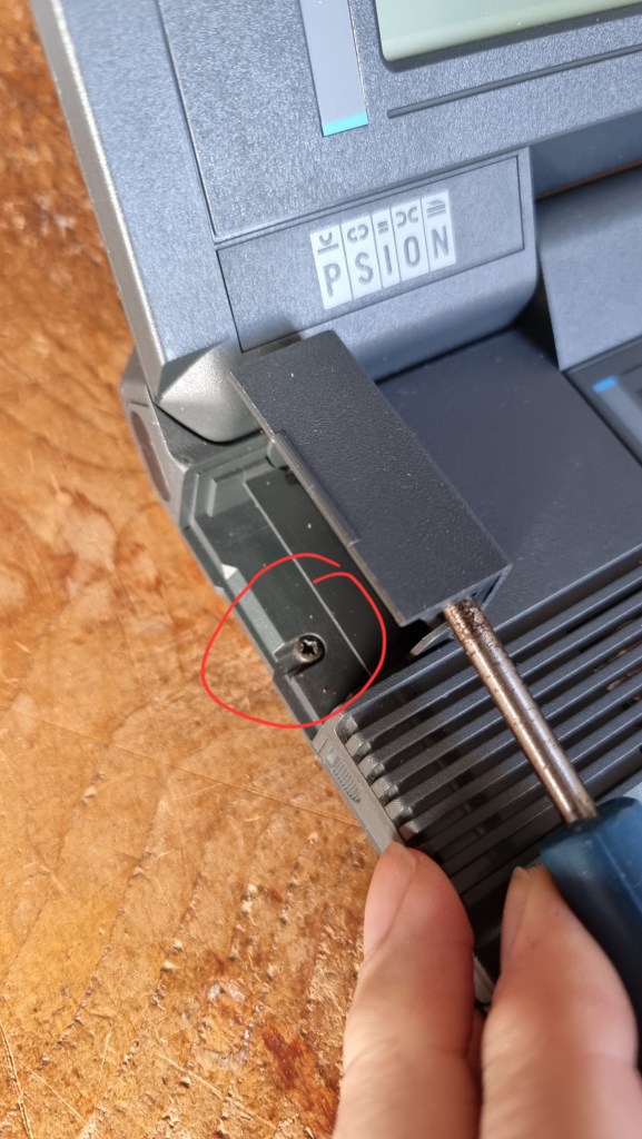
If the handle/stand is fitted then prise off the small rubber covers to expose the retaining screw and remove both screws and remove the handle

Lay the machine face down so the serial number label is uppermost
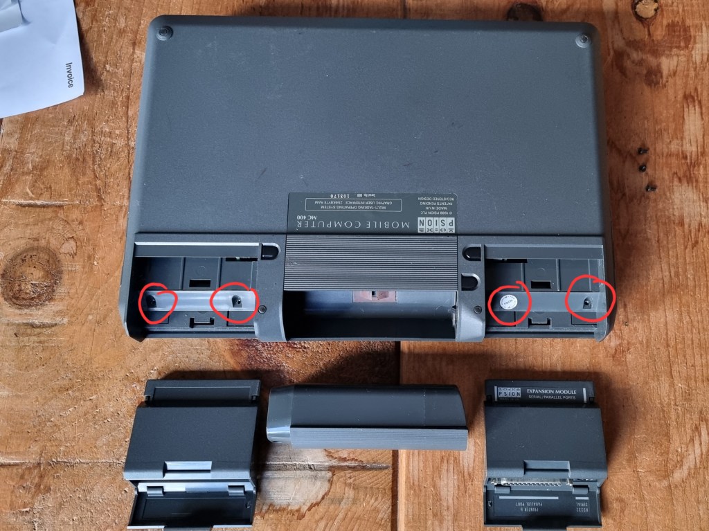
Remove 4 x screws – 2 each in both of the expansion ports
Turn the machine over, open the display lid
Remove 2 x screws – 1 each in each SSD bay

Remove the backup battery (3V CR1620 coin cell)

Close the lid and lay the machine face down and lift the lower case up at the rear by ~2cm

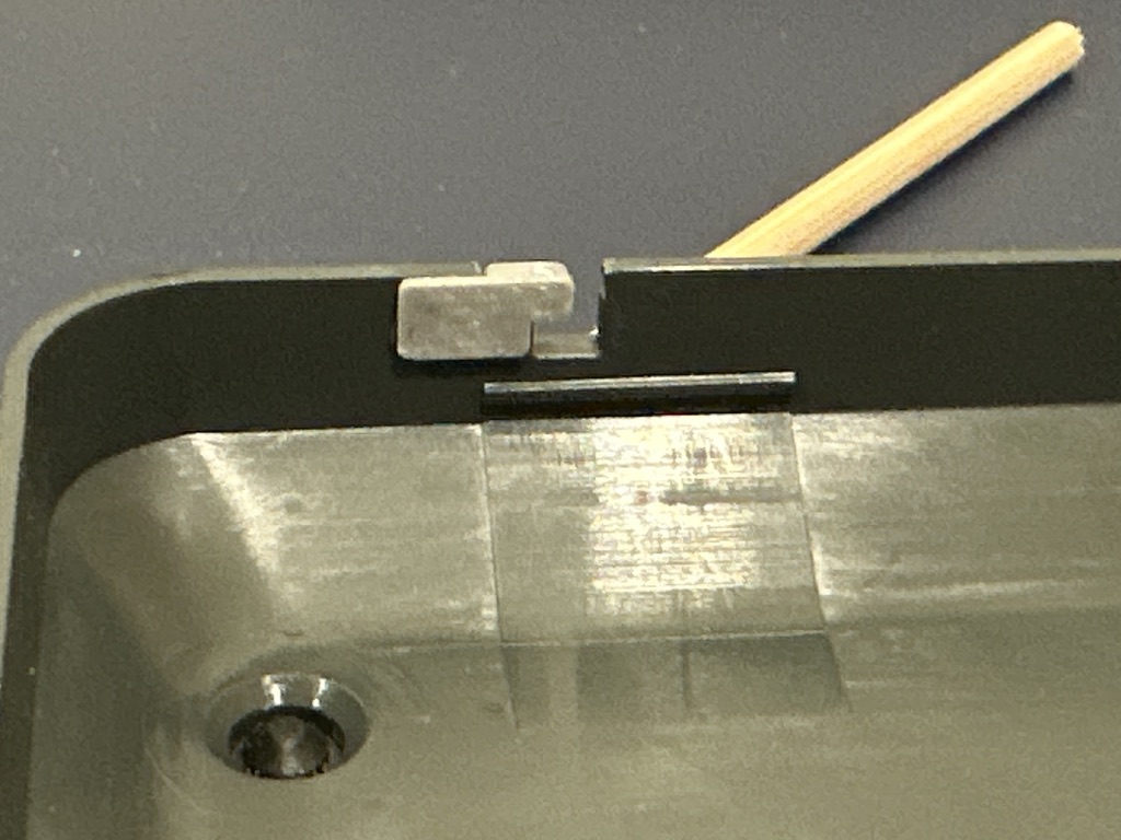
The front edge of the case has retaining clips, to release pull/slide the bottom panel towards the rear of the machine whilst keeping the rear edge elevated – this might be quite stiff. Take your time and keep wiggling/pulling the bottom panel.
The retaining clips that secure the base along the front edge are fragile – if anything breaks it’s likely to be these!
Side NOTE: If the plastic of the securing tabs does break @gw280 has made some 3D-printable tabs that should fix things…


Remove the single screw that secures the main PCB assembly & the touchpad

Remove the 4 x screws that secure the keyboard (1 at each corner)

Remove & place to one side the sliding doors on each side that cover MIC/SPKR/DC_IN and Fast serial port

Remove the two black plastic expansion module release buttons

Lift out the main PCB assembly, turn it over and lay it on top of the keyboard’s PCB
With a small flat blade screwdriver unclip the 2 18-way connectors (keyboard & display) and the 5-way connector (touchpad) & carefully slide out the ribbon cables


Lever the main PCB assembly away from its plastic shroud by levering near to the 2×9 connectors – one of the left hand side and another on the right hand side
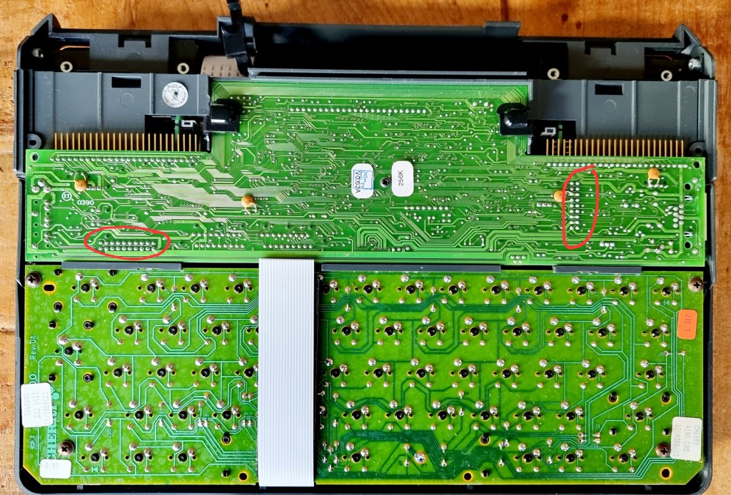
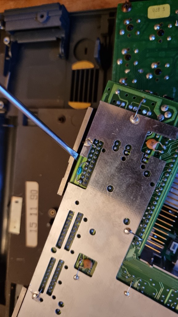
Location of the 18-way headers that connect the main PCB to the top plastic shroud and SSD bay connector PCBs.

Turn the machine over and open the display lid
Remove the 2 x trim panels (“PSION” logo and “M C 4 0 0”) that cover the hinge and LCD panel cover retaining screws. Push with the thumb on the outer edge which will expose a gap to get a flat screwdriver blade/spudger in to pop the panels off


Remove 4 x screws – 2 on each side to release the display panel outer cover
(The larger cross head screw is what determines the hinge friction – if your screen is floppy tighten this screw!)

Close the lid and lay the machine flat (lid uppermost) and lift the back edge of the display panel cover up by ~2cm

The front edge of the LCD panel cover has retaining clips, to release pull/slide the cover towards the rear of the machine whilst keeping the rear edge elevated – this might be quite stiff
To remove the LCD panel remove the 4 x screws (1 at each corner) and lift the LCD assembly out

<haynes manual>Assembly is the reverse of disassembly</haynes manual>
There are 4 micro-switches in the machine – 2 on the main PCB (one for each SSD door) and one on each SSD connector PCB (1 for each of the expansion module release buttons). The SSD door switches on the main PCB will need to be properly aligned by opening/closing the door before securing the long main PCB/touchpad screw.
Psion MC400 “Mobile Computer” – specifications at 1989 launch:
80C86 CPU 256k RAM 256k ROM
640×400 mono display – Retardation Film LCD, visible area 211 x 132 mm
4 x SSD drive bays (Psion proprietary RAM or FLASH SSD), clickable touchpad
12V external power, 7.2V Ni-Cd packs or 8 x AA,
40+ hours normal use per charge
60+ hours normal use on AAs
Instant On
Psion EPOC single user, pre-emptive multitasking OS
Sometimes referred to as the “MC GI” or “Graphic Interface” range…