

Recently I retrieved my Elektor SCMS “copybit killer” from storage and a quick Google search brought up this forum post from around a year before – someone was looking to build the project and needed a (binary) image of the ROM contents…

Initially I offered to physically send my ROM to someone with a dedicated reader (probably something from the TL866 family that seems to be popular amongst hobbyists) but then decided that seeing as I had breadboard, wires and plenty of small/embedded microcontrollers & Raspberry Pis lying around I really should have a go at reading the ROM myself!

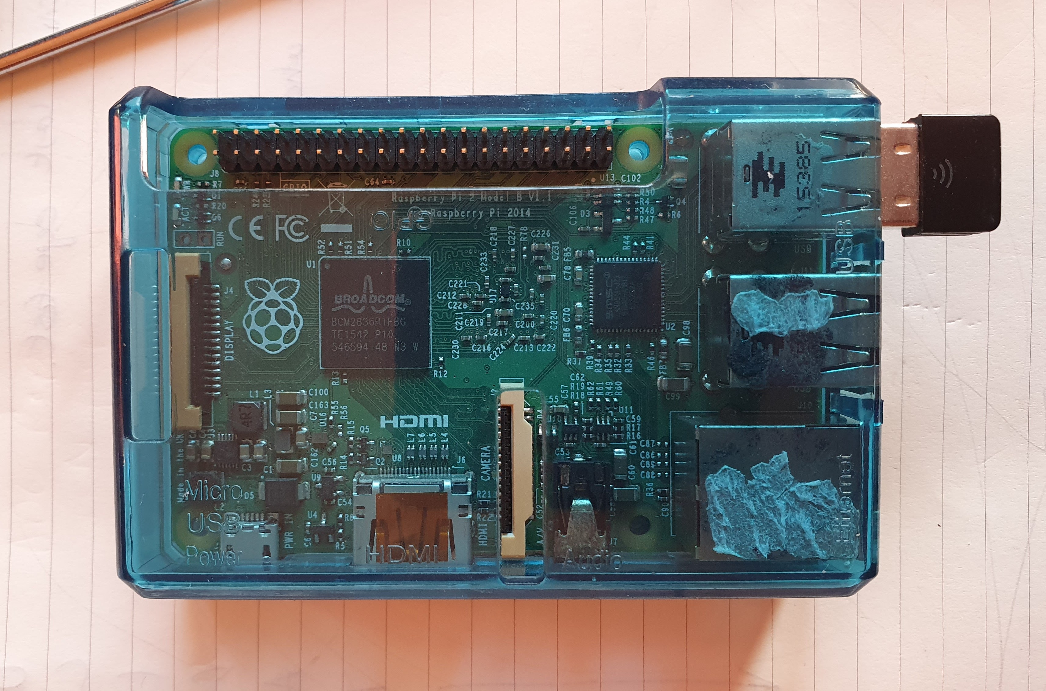
Old Pi Model 2B I’d been using as an LCD Clock – LCD removed ready to read ROM!
How hard could it be? Wire up the address & data buses to GPIO, step through all the addresses 0-65535 and record the data to a file. Easy. (If you ignore level-shifting issues that is 🙂 more about that later… )

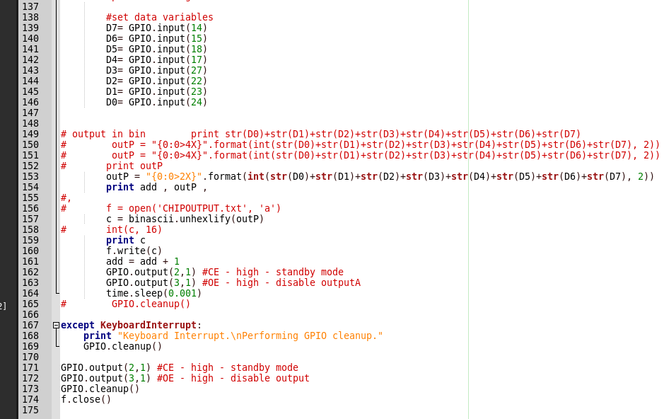
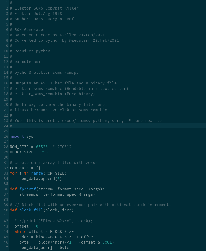
I discovered this post (which talks about dumping C64 ROMs & also references a previous Instructables.com article) which uses a Raspberry Pi… The Python on the site didn’t work quite right for me, I had to add some debug print statements to work out what was going on and then add some unhexlify from the binascii module to get an actually binary ROM image. There are other ways to do this (properly) but this was the first hack that worked for me, so it stuck. My python to read the chip is available to download below (“it’s not pretty, but it works” 😀 ):
Eventually it worked; I had a binary image of the ROM contents. The original Elektor article that refers to the Pascal used to generate the binary ROM contents mentions an output file size of 32768 bytes. My image is all zeros after 0x7FFF so I think it’s all good!
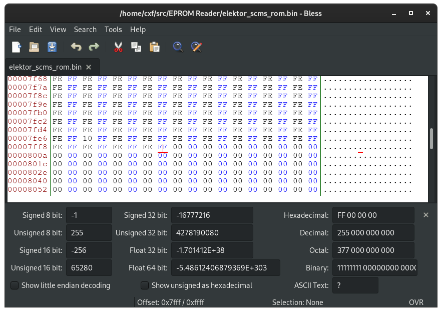
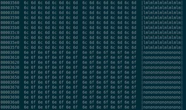
I wasn’t sure of the data integrity as the 27C512 is a 5V part and the Raspberry Pi’s GPIO is all 3V3 (and not 5V tolerant) and I had powered the ROM from 3V3 too. In the python script I’d inserted pauses of 1ms after setting the address/OE/CE before reading the data bus. Looking at the contents of my binary image it looks mostly sensible: it’s easier to judge by eye with this particular ROM due to its function as a finite state machine (FSM), it’s not just “random” binary data (like executable code might appear). There are some anomalies to the repeating patterns though: e.g. 0x7FE8 in the image above and a few other locations I’ve spotted too. I can’t say for definite at the moment if they are corrupt locations or good data.
UPDATE [2021-02-22]: turns out the “anomalies” are good data. Very good data. They’re the cool locations that do the magic! Thanks to the very clever people at the SonyInsider forums (well, Kevin Allen especially) – they reverse engineered the state machine function from the ROM contents and the S/PDIF spec… and even wrote some simple C code to generate the binary ROM contents. Truly epic work. I converted the C into python, (again, not pretty!) so we can at least re-generate the ROM image!
UPDATE [May/June 2021] the SonyInsider forums went offline for some weeks – here’s a link to a waybackmachine archive : https://web.archive.org/
UPDATE [June 2022] another ROM found in the wild and imaged: https://github.com/andydoswell/Elektor-976516-1 )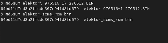
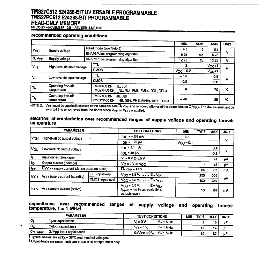
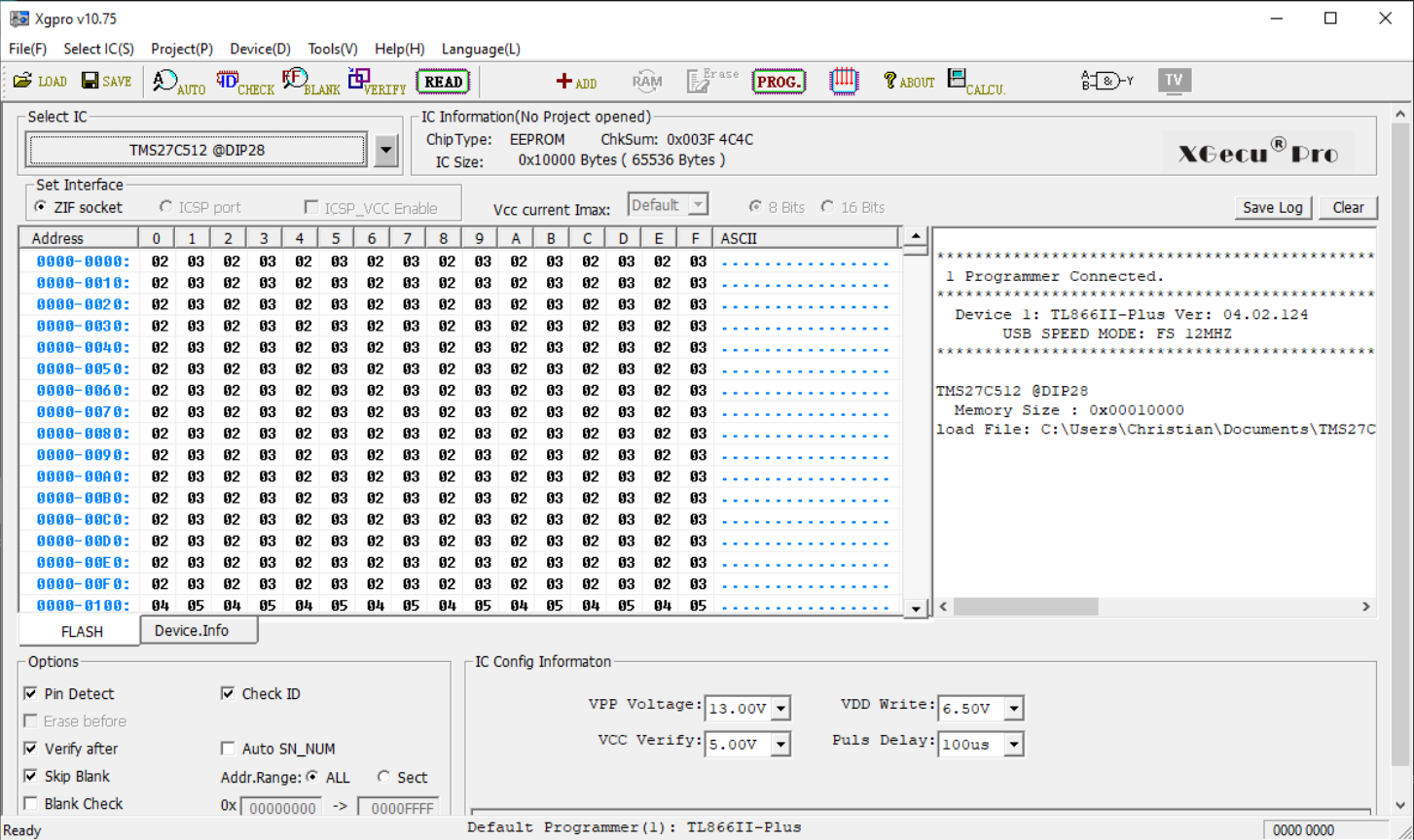
Back to the 5V ROM vs. the 3.3V Pi – “Datasheet says NO!” – minimum Vcc is apparently 4.5V… hmmm. To satisfy my curiosity I gave in and purchased a USB EPROM programmer (the TL866IIplus) and imaged the chip again. Looks like reading the 27C family slowly at 3V3 is viable as the image from the Pi and the USB reader are identical:
$ md5sum elektor_scms_rom.bin
64bd11d7cd3a2ffcde307e94fd8fd679 elektor_scms_rom.bin
$ md5sum TMS27C512@DIP28.BIN
64bd11d7cd3a2ffcde307e94fd8fd679 TMS27C512@DIP28.BIN
There are other ways around reading a 5V part in a 3V3 system – there are numerous level-shifting devices built into modules that can be placed between the ROM’s data outputs and the Pi’s GPIO, or a simple 2k2/3k3 resistor divider on each data line (address lines etc. can be driven directly from 3V3).

Conclusions:
Reading this particular device (Texas TMS27C512) directly with Raspberry Pi GPIO at 3V3, with Vcc=3V3 worked for me. It might not work with other manufacturers’ devices and/or other sizes of device. The original Elektor article sparked my hunt for the source which, via the fascinating work done on reverse-engineering the FSM operation from the S/PDIF spec, ultimately led to the C/Python code that can re-generate the binary ROM image.
Working with these old EPROM components took me right back to when I first started work in the Telecom industry and that was a long time ago 😀

2 thoughts on “Reading a 27C512 EPROM with a Raspberry Pi – ROM-dumping!”